1.4.2. Internal Components
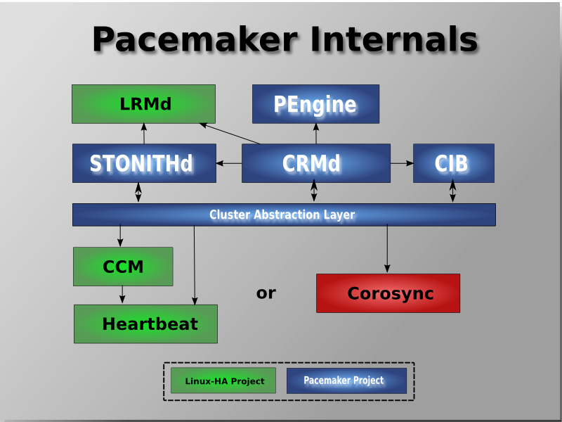
Pacemaker itself is composed of four key components (illustrated below in the same color scheme as the previous diagram):
CIB (aka. Cluster Information Base)
CRMd (aka. Cluster Resource Management daemon)
PEngine (aka. PE or Policy Engine)
STONITHd
The CIB uses XML to represent both the cluster’s configuration and current state of all resources in the cluster. The contents of the CIB are automatically kept in sync across the entire cluster and are used by the PEngine to compute the ideal state of the cluster and how it should be achieved.
This list of instructions is then fed to the DC (Designated Controller). Pacemaker centralizes all cluster decision making by electing one of the CRMd instances to act as a master. Should the elected CRMd process (or the node it is on) fail… a new one is quickly established.
The DC carries out PEngine’s instructions in the required order by passing them to either the LRMd (Local Resource Management daemon) or CRMd peers on other nodes via the cluster messaging infrastructure (which in turn passes them on to their LRMd process).
The peer nodes all report the results of their operations back to the DC and, based on the expected and actual results, will either execute any actions that needed to wait for the previous one to complete, or abort processing and ask the PEngine to recalculate the ideal cluster state based on the unexpected results.
In some cases, it may be necessary to power off nodes in order to protect shared data or complete resource recovery. For this Pacemaker comes with STONITHd.
STONITH is an acronym for Shoot-The-Other-Node-In-The-Head and is usually implemented with a remote power switch.
In Pacemaker, STONITH devices are modeled as resources (and configured in the CIB) to enable them to be easily monitored for failure, however STONITHd takes care of understanding the STONITH topology such that its clients simply request a node be fenced and it does the rest.